免责声明:本次截帧分析基于wuthering waves 的 runtime frame分析。优先分析角色shader,因此选取的截帧场景为角色展示界面。仅供个人学习,未用于商业用途。
1. 整体pass结构
从renderpass上来看,完整的render流程可以拆分为:
- compute pass 1
- color pass 1
- color pass 2 basepass 负责gbuffer: 1 * final rt + 6 * data rt + 1 * Depth
- depth – only pass 1 + compute pass 2
- depth – only pass 2 (shadow map)
- depth – only pass 3 produce 一个10240 * 2048 的 D16 buffer
- some unused draw + color pass 3
- light composite 接收 5 * data rt,输出到 final rt
- color pass 4 特效合成pass
- compute pass 3
- post processing:bloom,SSAO…
- color pass 5:linear to RGB + UI painting
流程中含有大量的compute shader优化内容,以及疑似compatible残留下来的,unused feature
2. basePass细节
1. 组成角色的组件(以daniya为例说明)
face01(12948)- 自然是脸 draw两次,有outline
fur(10902) – 披肩毛茸茸效果
up01(59412)- 角色body
down01(54150)- 角色正面衣裙
cloth(83844)- 角色衣服,是面数最多的组件
eye01(1530)- draw两次,但没有outline
bangs(刘海?但实际是整个头发) – 特殊处理,被draw了3遍(不算outline)
- 第一次draw只写入了normal rt的B通道,用于处理刘海产生的面部阴影
- 第二次draw是主体draw
- 第三次draw防止eye覆盖在bang上面
hair01 – 正常的 draw 1次
(bangs hair01 down01 cloth face01 up01 有 outline draw, fur eye01没有)
这些部件对应的shader可以归类为3个基类:
MSM_ToonCommon:up down fur cloth 最复杂的shader 3000 – 5000 dxil lines
MSM_ToonHair:hair bangs 3000 lines(bangs的第一个draw非常简单,只有300 lines)
MSM_ToonFace:eye01 face01 第一次1000 – 2000 dxil lines 第二次500lines(但这个第二次draw是unused)
2. MSM_ToonCommon
shader的texture slots比较统一,下面以cloth为例说明
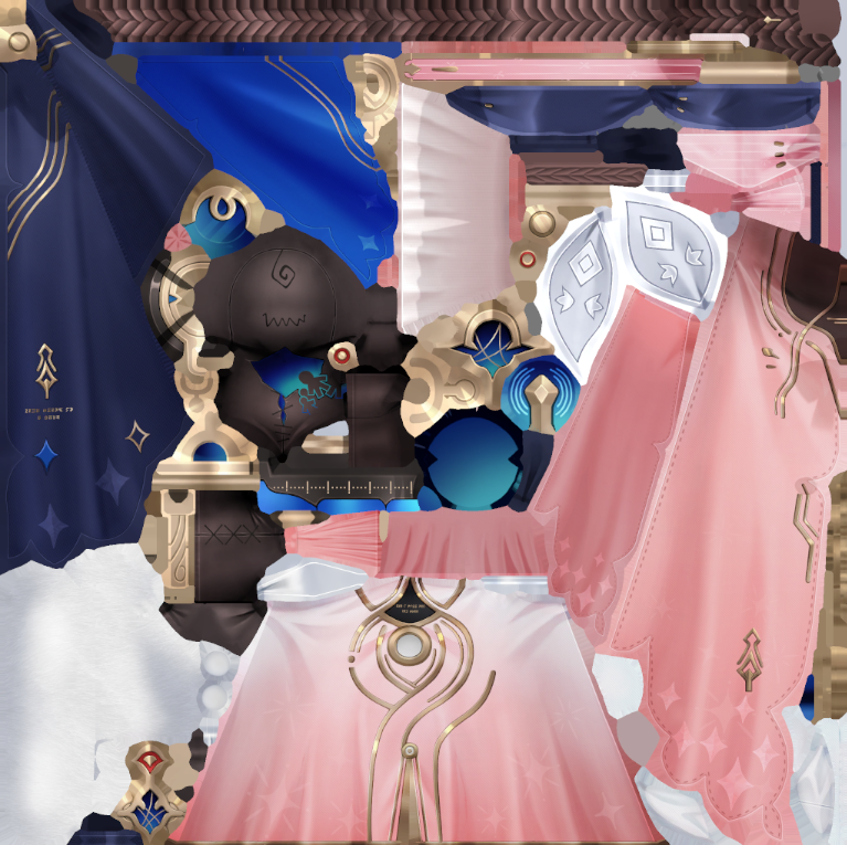
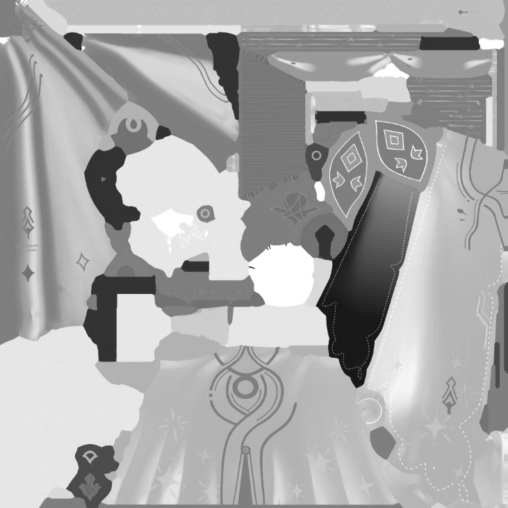
Cloth_D.rgb diffuse
Cloth_D.a
Cloth_D.rgb是基础颜色通道,没什么特别的。
Cloth_D.a 控制区域高光,呼吸灯效果
float a = Cloth_D.a;

// 高段 mask,a < 0.9,值为 0,a 从 0.9 到 1 ,highmask 从 0 到 1
highMask = (min(max(a, 0.9), 1.0) - 0.9) / 0.1;

// 作为高光项贡献到最终色中
effectRGB = effectColor * highMask * litColor;
finalColor += effectRGB / breath-modulated contribution;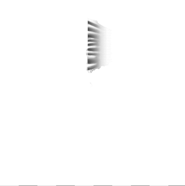
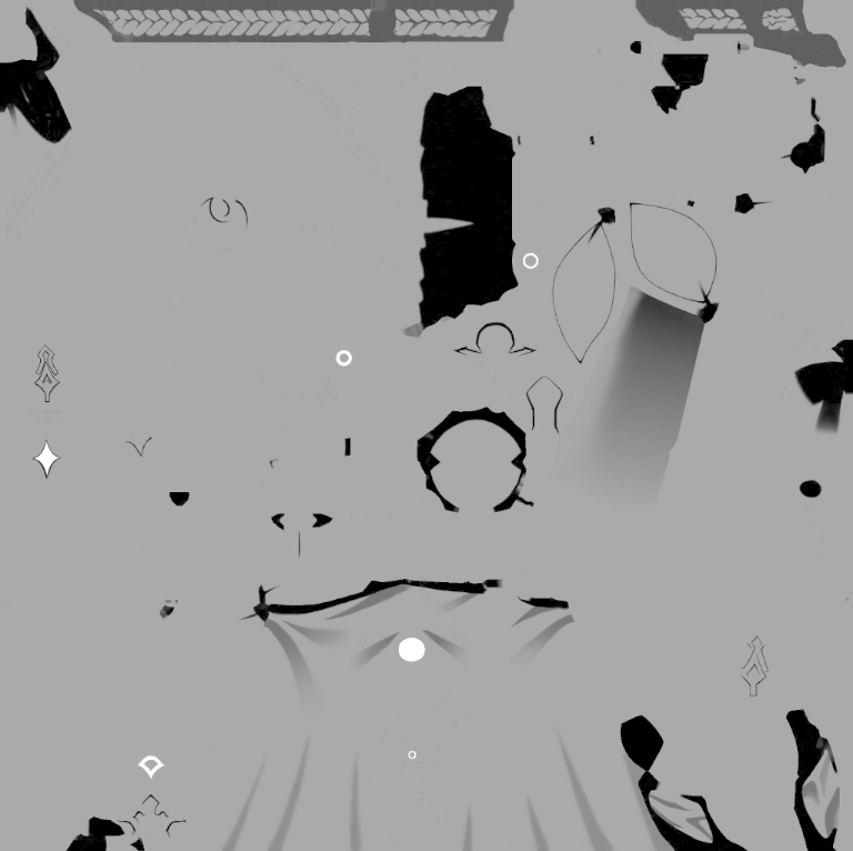
Cloth_FTM.r
Cloth_FTM.g
Cloth_FTM.b
Cloth_FTM.a
FTM是type mask,4通道承载着不同的作用
- r通道:
FTM.r越高,该像素越不容易被 dither/discard 掉;值越低,越依赖高光亮度或噪声决定是否保留
ftmR = Cloth_FTM.r;

clipStrength = max(specLuminance, ftmR);
discard if (clipStrength + noise + threshold < 0);- g通道:metallic贴图,最终的metallic是region id决定的metallic + g通道采样决定
ftmG = Cloth_FTM.g;

pbrRate = regionMetallicBase + ftmG;
pbrRate = saturate(pbrRate * 1.11111);

matcapMultiplier.rgb =
    1.0 + (matcapColored.rgb * baseSpecTint.rgb - 1.0) * pbrRate;

specTerm.rgb =
    lobeShape
  * baseSpecTint.rgb
  * matcapMultiplier.rgb;

extraSpec.rgb = max(specTerm.rgb * materialMask - 1.0, 0.0);- b通道:法线细节程度,即法线是更接近基础法线,还是更接近 Cloth_N.rg 的细节法线。选择逻辑公式:,说明高值使法线更靠近基础/顶点法线,视觉更平;低值保留更多
Cloth_N.rg的细节。当前cloth中没有启动blend,也就是默认法线全部来自Cloth_N.rg - a通道:配合region id,以及平滑材质边界
ftmB = Cloth_FTM.b;

normalBlendMask =
    saturate(cb4[114].y * 2.00803 *
    (cb4[114].x * (ftmB - 0.5) - 0.00199997));

detailNormal = decodeNormal(Cloth_N.rg);
finalNormal = lerp(detailNormal, baseNormal, normalBlendMask);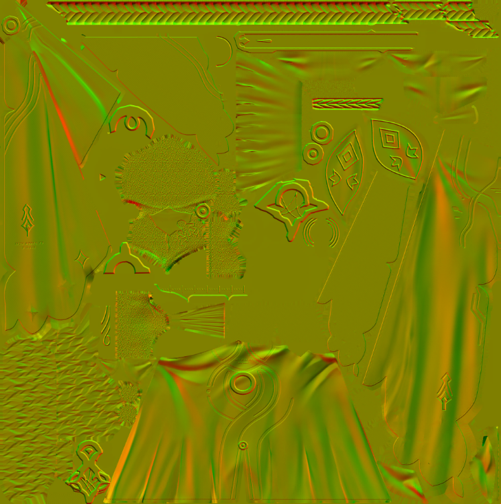
Cloth_N.rg
Cloth_N.a
Cloth_N.rg uv采样的细节法线
Cloth_N.a roughness控制,影响高光区域和flowmap采样LOD。可以看到,a通道越接近 1 说明LOD越高,也就是采样的越模糊,最终响应就越低频,代表roughness提高
response = saturate_to_0_1(
    clamp(regionRoughness + Cloth_N.a, 0.0, 0.9) / 0.9
);
matcapLOD = 4.0 + 1.2 * log2(max(response, 0.001));

response = 1.0   -> LOD = 4.00
response = 0.5   -> LOD = 2.80
response = 0.25  -> LOD = 1.60
response = 0.1   -> LOD = 0.01
response = 0.001 -> LOD = -7.96,实际接近最清晰 mip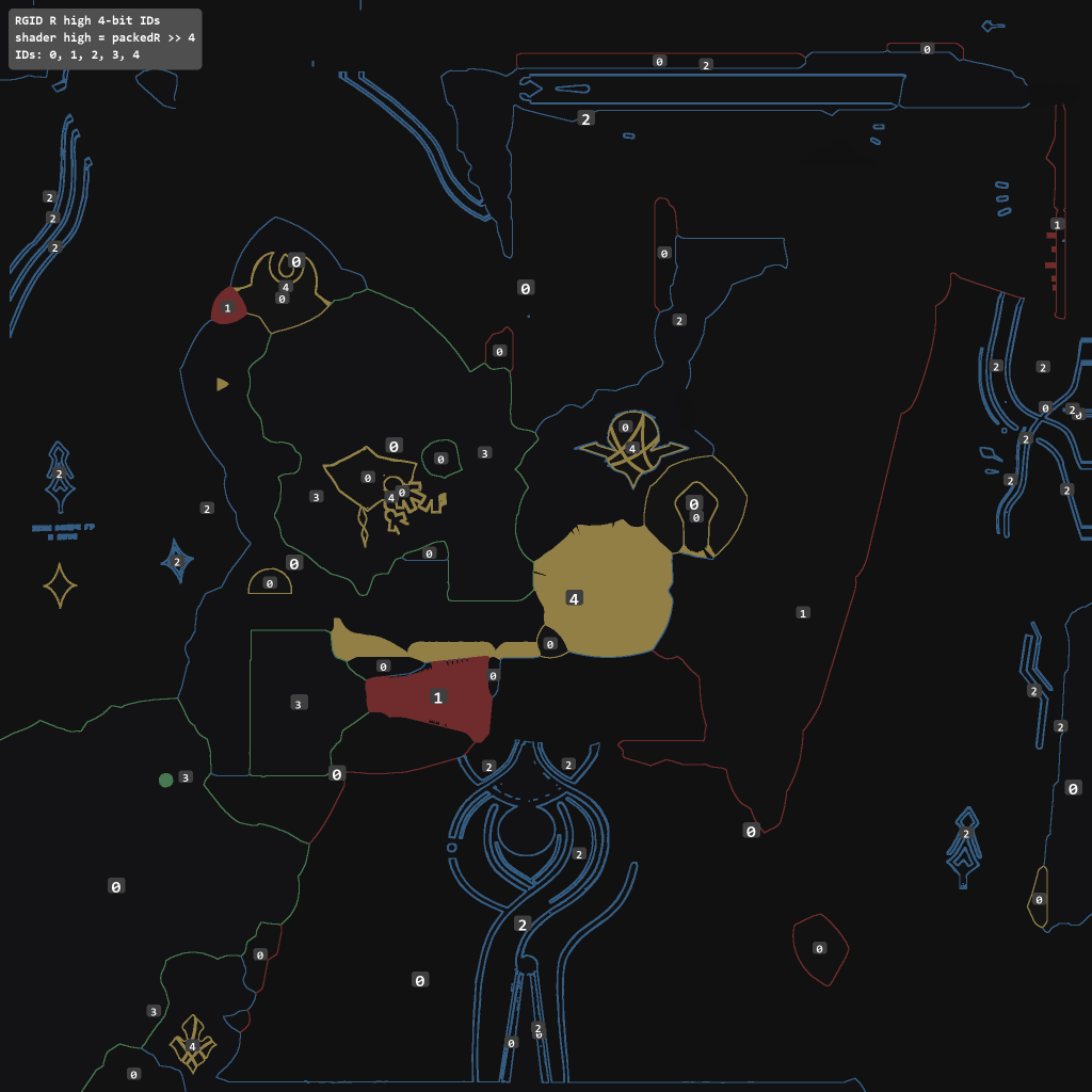
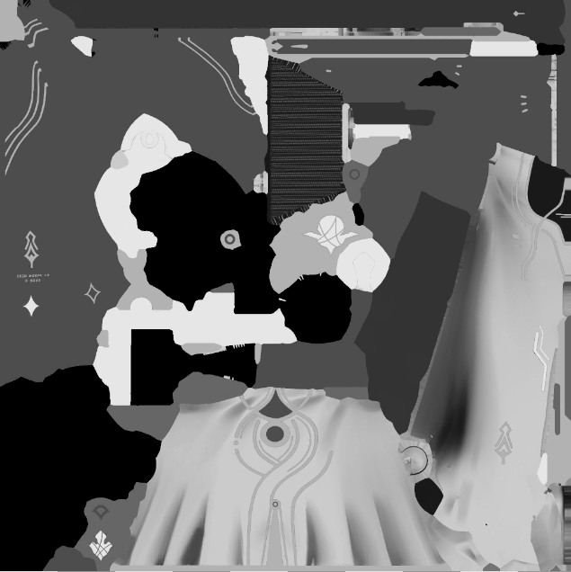
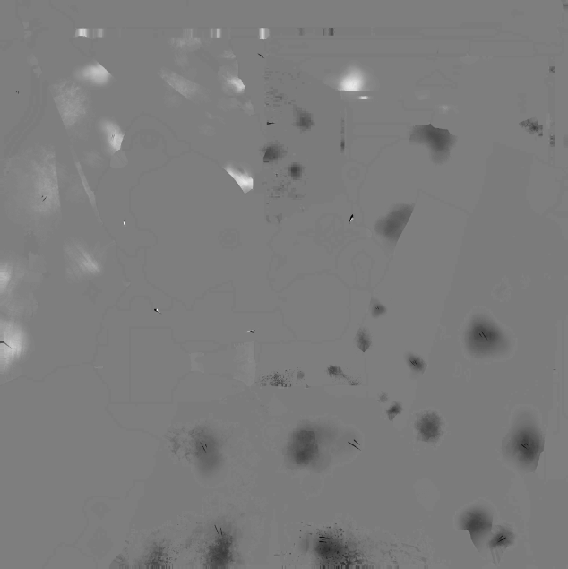
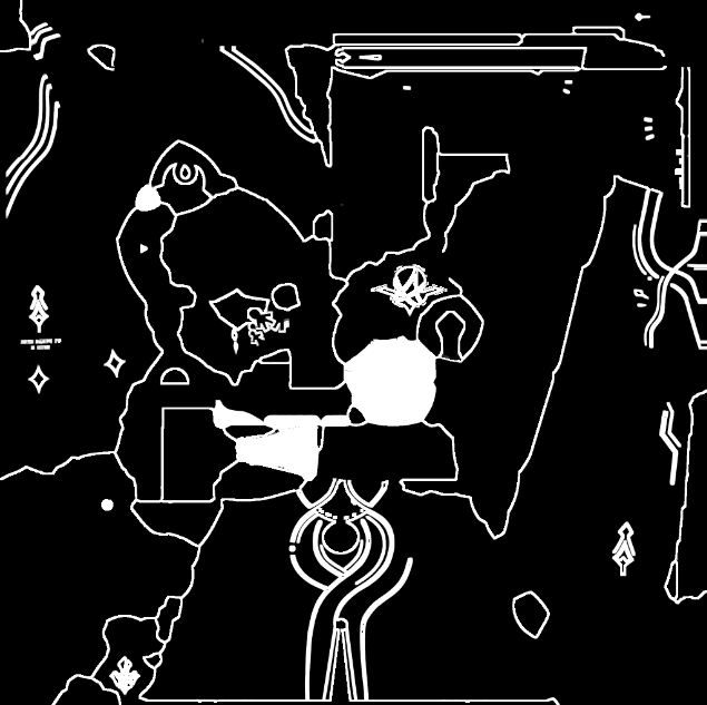
RGID_high4.r
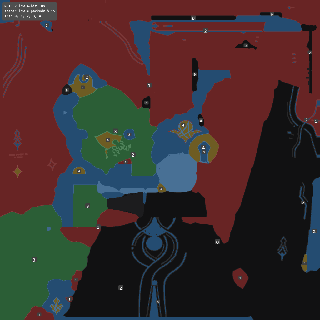
RGID_low4.g
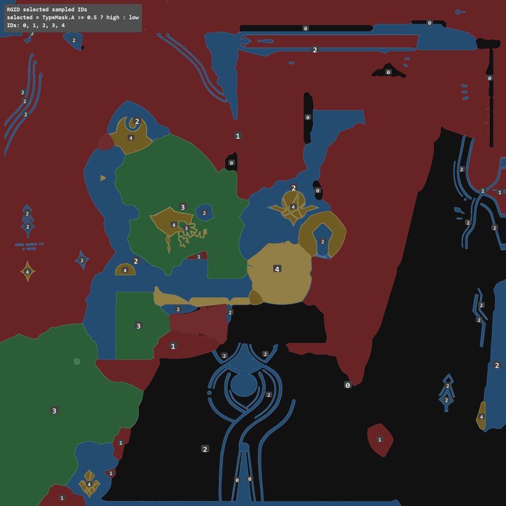
RGID_selcted.b
RGID贴图,与 Cloth_FTM 贴图的a通道配合使用。其本身每个像素是8bit的单通道值,前面4bits和后面4bits分别编码两组region id,即如上图所示。region id范围是 0 – 4
decode时,需要经过一个判断:当Cloth_FTM.a大于0.5,即白色区域,choose high;反之choose low。最终的region id如上右图所示。
region id绑定了一组对应的参数集合。从Cloth对应的材质实例(Material Instance)来看,这组参数是:
id 0: RampID 2, RampInt 0.7, ShadowWidth 0.1, Metallic -0.2, Roughness 0.2, Spec_Int 1, Spec_Smooth 1.0, Spec_Width 0.5
id 1: RampID 2, RampInt 0.5, ShadowWidth 0.5, Metallic -0.1, Roughness 0.0, Spec_Int 1, Spec_Smooth 1.0, Spec_Width 0.5
id 2: RampID 2, RampInt 0.5, ShadowWidth 0.1, Metallic -0.1, Roughness 0.0, Spec_Int 1, Spec_Smooth 0.1, Spec_Width 0.5
id 3: RampID 2, RampInt 0.1, ShadowWidth 0.5, Metallic 0.0, Roughness 0.0, Spec_Int 1, Spec_Smooth 1.0, Spec_Width 0.5
id 4: RampID 2, RampInt 0.5, ShadowWidth 0.1, Metallic 0.0, Roughness 0.0, Spec_Int 1, Spec_Smooth 1.0, Spec_Width 0.5
但有几个开关控制这里:
“UseIDMetallicParam”: 0.0, “UseIDRoughnessParam”: 0.0,
Normal_Flowmap_40001_2.rgb
Normal_Flowmap_40001_2.a
Rim light feature
二选一:当前情况下,region id决定了regionMatcapMask,也就决定了是选择这里的彩色项,还是灰度项
region id 0: 使用 Normal_Flowmap_40001_2.rgb 让裙子粉色的部分更富有彩色变化
region id 1-4: 更倾向使用 Normal_Flowmap_40001_2.a 灰度
采样值来源于:法线正对镜头的程度,也就是当法线正对镜头是,取texture正中央;当法线近似于镜头垂直的时候,取texture最边缘。
两个结论:
- 裙子粉色部分(id 0)更接近漫反射颜色,rim light部分特性不明显
- 其他部分的rim light项没有颜色倾向,仅仅负责在边缘时亮的feature
id = selectedRegionID;

regionMatcapMask =
    (id + 0.5 >= 1.0) &&
    (id - 0.5 <= 4.0)
        ? 1.0
        : 0.0;
projectedX = normal.x * view.z - normal.z * view.x;
projectedY = normal.z * view.y - normal.y * view.z;

matcapUV = float2(projectedX, projectedY) * 0.5 + 0.5;

matcapSample = Normal_Flowmap_40001_2.SampleLevel(matcapUV, matcapLOD);

// 这里lerp由于mask是0/1,实际就是2选1
matcapRGB = lerp(
    matcapSample.rgb,
    matcapSample.a.xxx,
    regionMatcapMask
);

matcapColored = matcapRGB * MatcapColor.rgb * matcapIntensity;
specTerm += matcapColored * regionSpecParams;
Normal_Flowmap_40001_N.rg
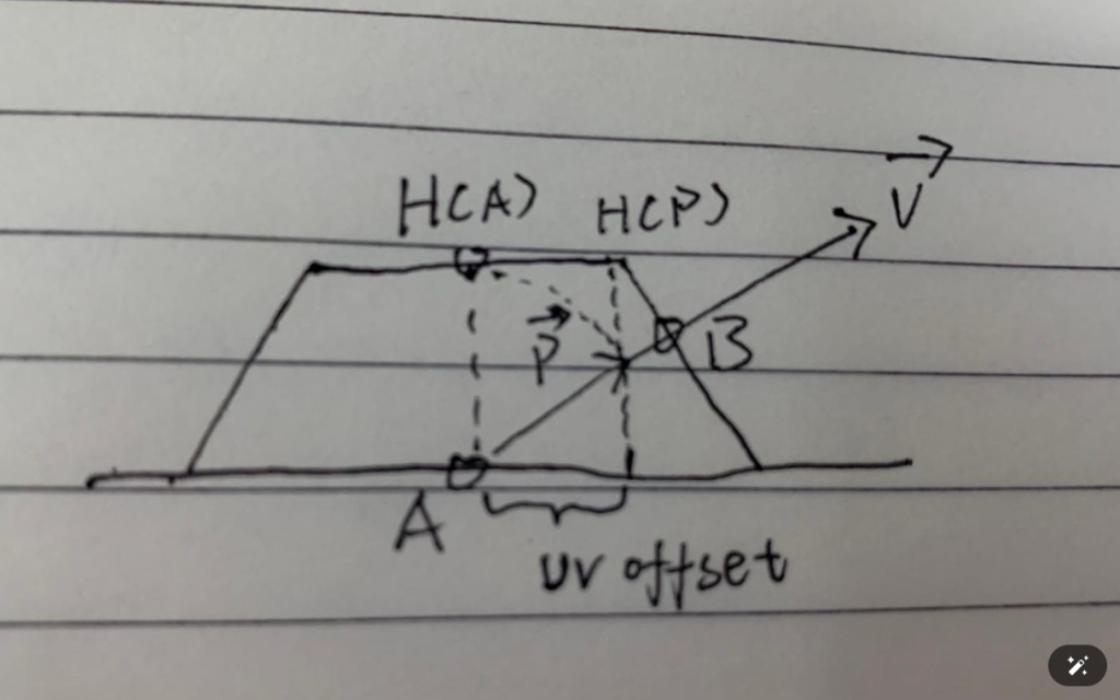
feature:这是 Parallax Mapping(视差贴图) 的一种变体。
真实几何里,如果布料表面有凸起、绒毛、纹理沟槽,斜着看时,你看到的并不是原始 UV 那个点,而是视线穿过表面高度场后碰到的另一个点。如下图,此时采样A就不太对,应该采样B,于是需要计算出uv offset
对于特定的region id,采用这个flow map 直接影响主 uv 让纹理偏移。cloth下,region id = 3 触发
沿视角方向做多步 raymarch,每一步用 flowmap.rg 给这个步进位置一个局部方向扰动,再结合高度/遮罩决定最终 UV 偏移。这个高度实际是 T_Sparkle_SDF 的 r 通道,为了模拟布料,大概是这样的:
flowRegionMask = (regionID == 3) ? 1.0 : 0.0;

// tangent space view slope,视角越斜,UV 偏移越大
viewOffset.x = -dot(viewDir, tangent)   / dot(viewDir, normal);
viewOffset.y = -dot(viewDir, bitangent) / dot(viewDir, normal);

parallaxStrength = 0.005333 * flowRegionMask;

// 先把起点从 baseUV 往视角反方向推一点
uv0 = baseUV - viewOffset * parallaxStrength;

if (flowRegionMask == 1)
{
    float uvScale = 30.0;
    float stepCount = 8.0;
    float layerStep = 1.0 / stepCount;

    // 实际循环次数是 stepCount + 2 = 10 步
    int loopCount = 10;

    float2 rayStepUV = viewOffset * 0.005333 / stepCount;

    // 注意:height/SDF 采样用的是 30 倍 tiled UV
    float2 scaledBaseUV = uv0 * uvScale;

    float currentLayer = 1.0;
    float prevLayer = 1.0;
    float prevHeight = 1.0;

    float2 prevOffsetScaled = 0;
    float2 finalOffsetScaled = 0;

    // shader 里还有一个 facing mask,大致是视角/法线相关的 smoothstep
    // 不朝向合适方向时,height 会被压低
    float heightMask = smoothstep01(saturate(NoV_like)) * flowRegionMask;

    for (int i = 0; i < 10; i++)
    {
        // flowmap 采样:沿 viewOffset 方向往前走
        float2 rayUV = uv0 + rayStepUV * (i + 1);

        float2 flowVec =
            T_Normal_Flowmap_40001_N.SampleGrad(sampler, rayUV, ddx, ddy).rg * 2.0 - 1.0;

        // 这里 0.08 / 8 = 0.01
        float2 flowOffsetScaled = flowVec * 0.01;

        // height / SDF 采样:不是 rayUV,而是 scaledBaseUV + 上一步 offset
        float2 heightUV = scaledBaseUV + prevOffsetScaled;

        float height =
            T_Sparkle_SDF.SampleGrad(sampler, heightUV, ddx, ddy).r
          * heightMask;

        // 核心判断:
        // currentLayer 从 1.0 开始,每步减 1/8
        // height 是当前 SDF/height 纹理给出的高度
        // 如果 currentLayer < height,说明 ray 已经进入/穿过 heightfield
        bool hit = currentLayer < height;

        if (hit)
        {
            float hitT =
                (height - currentLayer)
              / ((prevLayer - currentLayer) - prevHeight + height);

            // 命中后在上一层和当前层之间插值,减少 8 步 raymarch 的阶梯感
            finalOffsetScaled =
                prevOffsetScaled
              - hitT * (rayStepUV * uvScale - flowOffsetScaled);

            break;
        }
        else
        {
            // 没命中就继续推进。
            // 注意它不是简单 accumulated += flowOffset;
            // shader 会把 ray 步进 offset 和 flowmap offset 组合成新的候选 offset。
            finalOffsetScaled =
                rayStepUV * uvScale * (i + 1)
              + flowOffsetScaled * (10.0 - i);

            prevOffsetScaled = finalOffsetScaled;
            prevLayer = currentLayer;
            prevHeight = height;

            currentLayer -= layerStep;
        }
    }

    finalUV = uv0 + finalOffsetScaled / uvScale;
}
else
{
    finalUV = baseUV;
}
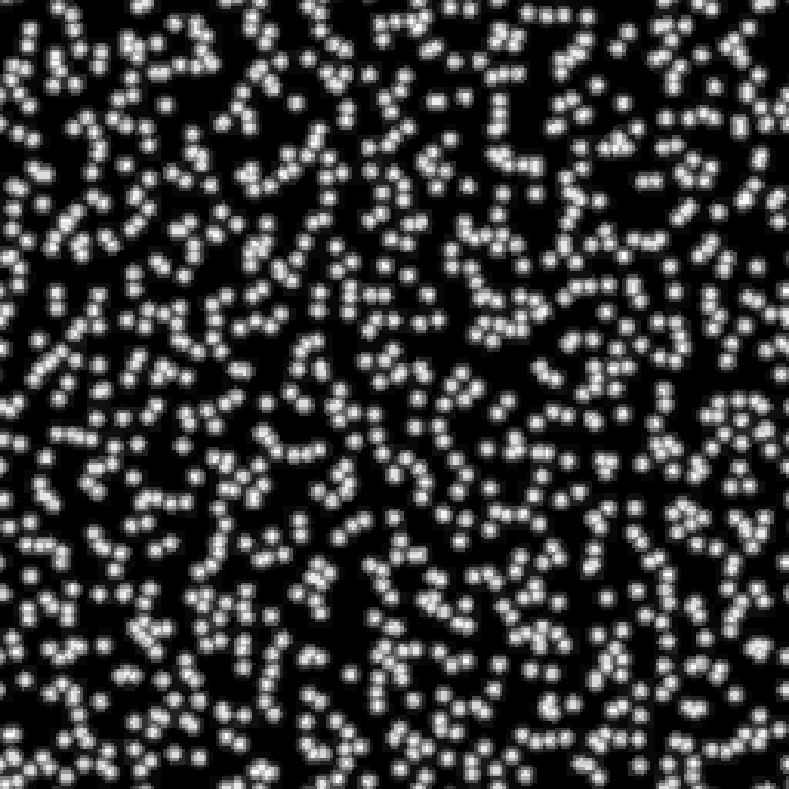
T_Wenli_230046
T_Wenli_230046 是一层会随物体/屏幕坐标滚动的 second texture,当前参数让它 横向重复 4 次、纵向重复 2 次,并按时间缓慢滚动,然后染成偏蓝紫的颜色。
1. 先构造 Second UV
当前开关:
UseSecond = true;
Second_UseObjectScreenUV = true;
Second_UseScreenUV = 0;
所以它用的是 object-screen UV 这套坐标,不是普通主 UV。
object-screen UV 理解:屏幕空间内,当前pixel与center的距离
// 当前像素/当前片元的某个 view/object relative 位置
float3 p = pixelRelativePos;        // 对应 _353,_354,_355

// 物体/角色基准点,来自 cbuffer
float3 center = objectCenterOrPivot; // 对应 cb2[5].xyz / _1606,_1607,_1608

// 把当前点投影到屏幕
float2 screenP;
screenP.x = ProjectX(p);
screenP.y = -ProjectY(p);

// 把物体基准点投影到屏幕
float2 screenCenter;
screenCenter.x = ProjectX(center);
screenCenter.y = -ProjectY(center);

// 两者相减,得到 object screen uv
float2 objectScreenUV = screenP - screenCenter;

// 然后 shader 会按距离/深度做一次缩放:
depthScale = abs(ProjectDepth(center + cameraPos) * 0.01);
objectScreenUV *= depthScale;
然后带入 Second_ScreenObjectUV = float4(0,0,1,0.7)
objectScreenUV =
    (Project(pixelPos) - Project(objectCenter))
  * depthScale
  * float2(1.0, 0.7)
  + 0.5;
2. 再带入 Second_UV.xy = (4, 2)(基础缩放) 和 Second_UV.zw (滚动速度)
secondUV = objectScreenUV * float2(4.0, 2.0)
+ timePhase * float2(0.03, 0.02);
3. 采样 T_Wenli_230046
secondSample = T_Wenli_230046.SampleBias(secondUV).rgb;当前 second 处理参数里 power / blend 基本不会改变采样颜色:
power = 1.0;
intensityA = 1.0;
intensityB = 1.0;
blend = 0.0;

secondRGB ≈ secondSample.rgb;
4. 带入 Second_ColorTint = (1.2, 1.9, 4.0)
secondTinted.rgb = secondRGB * float3(1.2, 1.9, 4.0);也就是:
R *= 1.2;
G *= 1.9;
B *= 4.0;
直观理解:蓝通道被放大最多,所以这层 T_Wenli_230046 最终偏蓝/青紫,像一层额外发光纹理或流动纹理。
举个像素例子:
objectScreenUV = float2(0.2, 0.6);

uvTiled.x = 0.2 * 4.0 = 0.8;
uvTiled.y = 0.6 * 1.4 = 0.84;

secondUV = float2(0.8, 0.84) + float2(3.247, 2.165);
secondUV = float2(4.047, 3.005);

// wrap 后约等于
secondUV = float2(0.047, 0.005);
如果这时采样到:
secondSample = float3(0.5, 0.3, 0.1);染色后就是:
secondTinted = float3(
  0.5 * 1.2,
  0.3 * 1.9,
  0.1 * 4.0
);

secondTinted = float3(0.6, 0.57, 0.4);
最后它还会再乘 rim/view mask、其它 second mask,然后加到最终颜色里。简化链路就是:
objectScreenUV
 -> * float2(4.0, 1.4)
 -> + time * float2(0.03, 0.02)
 -> sample T_Wenli_230046.rgb
 -> * float3(1.2, 1.9, 4.0)
 -> mask/rim 调制
 -> finalColor += secondContribution
这组参数让 T_Wenli_230046 作为一层随时间滚动的 second 纹理覆盖在布料上,横向密度更高,颜色被强烈推向蓝色,用来做额外纹理/光纹效果。